Harmony Machine
I am working on a project as part of my coursework in which I need to create a prototype for a installation. The installation must tell a narrative through non-traditional techiniques and must be executed using computer technolocgies. I have decided to design an installation called Harmony Machine.
Resources left to use:
Sonar project on Arduino Project Hub
Tuesday 25th November
Servo & Ultrasonic Sensor
Getting the servo up and running was actually quite easy. Plugged servo into the groud and 5v power ports, as well as digital port 9.
I copied this sweep code from the Arduino website into the IDE.
#include (arrow bracket)Servo.h(arrow bracket)Servo myservo; // create servo object to control a servo// twelve servo objects can be created on most boardsint pos = 0; // variable to store the servo positionbool servoOn = true; //an on and off swtitch so the servo doesn't drive me mad while workingvoid setup() {myservo.attach(9); // attaches the servo on pin 9 to the servo object}void loop() {if(servoOn == true) { // if func to make on/off 'switch' workfor (pos = 0; pos (lessthan)= 180; pos += 1) { // goes from 0 degrees to 180 degrees// in steps of 1 degreemyservo.write(pos); // tell servo to go to position in variable 'pos'delay(15); // waits 15ms for the servo to reach the position}for (pos = 180; pos >= 0; pos -= 1) { // goes from 180 degrees to 0 degreesmyservo.write(pos); // tell servo to go to position in variable 'pos'delay(15); // waits 15ms for the servo to reach the position}}}Output:
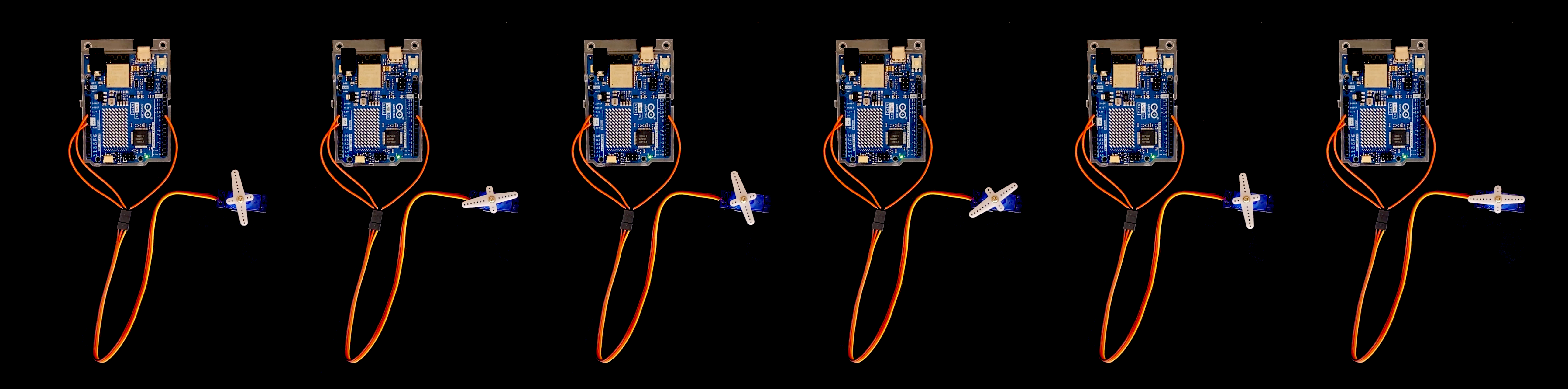
This worked perfectly causing the servo to rotate back and forth a total of 180 degrees.The next step will be to connect the motion sensor and find a way to mount it to the servo.
First thing I did was check to see if the Ultrasonic Sensor was working. I went back to this handy guide on the Arduino Project Hub that I had first used during one of the workshops to get the sesor up and running.
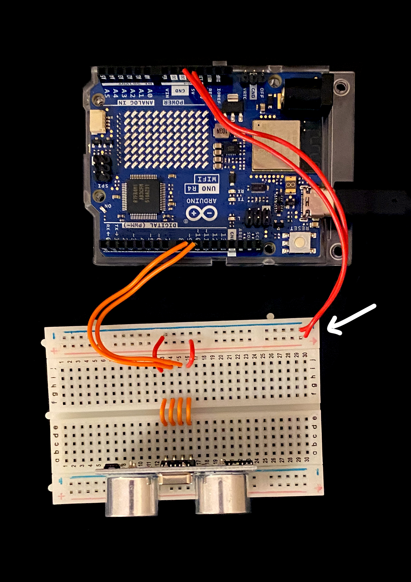
I set the sensor up in this configuration, following the diagriam and code from the link above. Code in the IDE:
const int trigPin = 9;const int echoPin = 10;float duration, distance;void setup() {pinMode(trigPin, OUTPUT);pinMode(echoPin, INPUT);Serial.begin(9600);}void loop() {digitalWrite(trigPin, LOW);delayMicroseconds(2);digitalWrite(trigPin, HIGH);delayMicroseconds(10);digitalWrite(trigPin, LOW);duration = pulseIn(echoPin, HIGH);distance = (duration*.0343)/2;Serial.print("Distance: ");Serial.println(distance);delay(100);}After spending a while convinced I had set up the sensor correctly but recieving only 'Distance: 0.00' in the seria monitor I realised that I had the bread board around the wrong way, effectively swapping the 5V and GND cables. I uplugged everything and reconstructed and followed the diagram again keeping this in mind. It wasn't until this point that I realised I may have mixed up the Trig and Echo pins within the code. Unfortuntaley I tried swapping around pins 9 and 10 in the code and it did not fix the problem.
The next step will be to grab a sensor from someone else and see if something is wrong with the hardware as I'm really not sure there's anything wrong with me code.
Monday 24th November
Rasterizing in Processing
Following this video by Tim Rodenbroeker I created a grid in Processing and then used brightness data from the pixels within a photo to draw shapes within the grid. This created a nice 'computerised' effect, but will also allow me to distort the image with an input from the Ultrasonic Sensor.